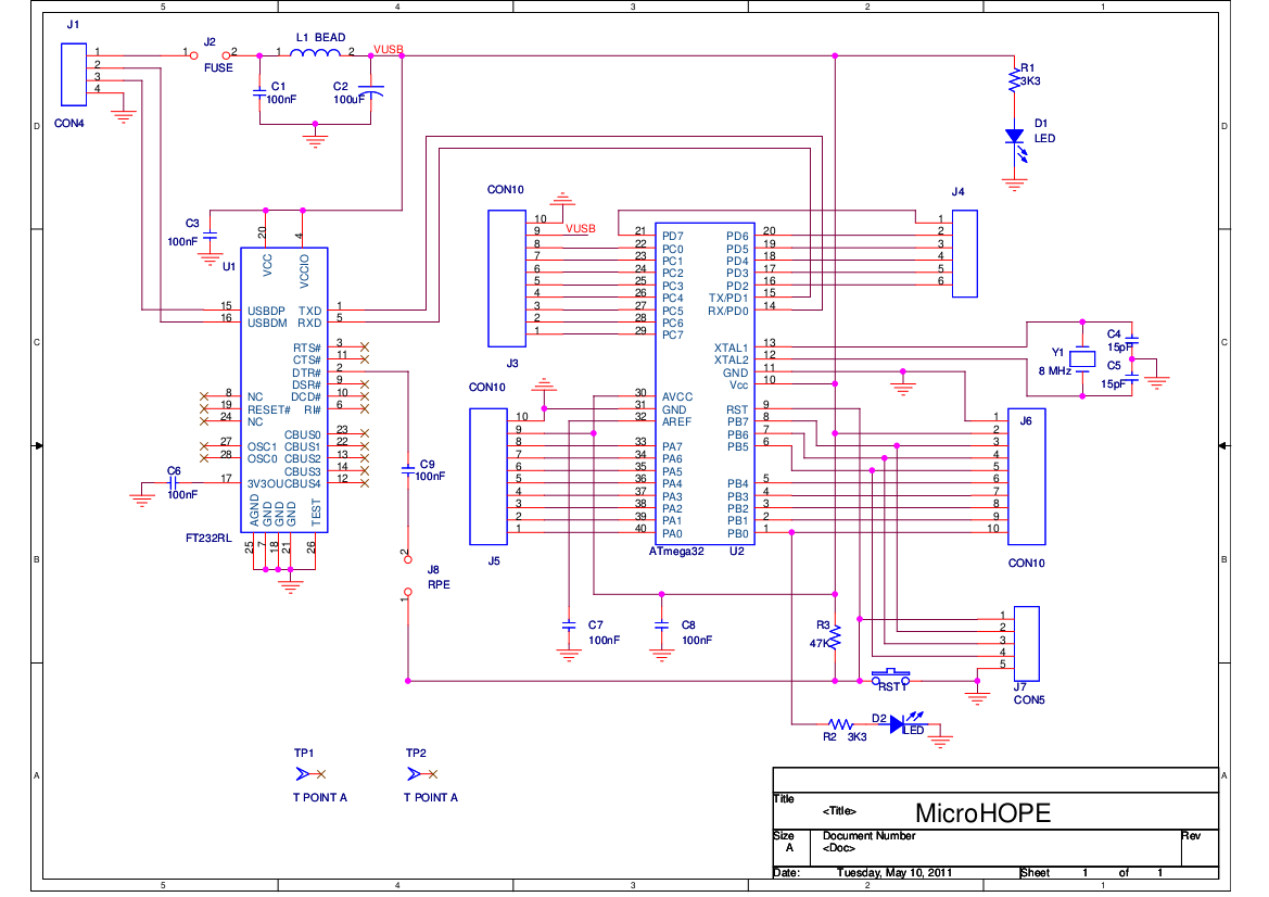
The block diagram of the MicroHOPE hardware is shown below. ATmega32 has 32 General Purpose Input/Output pins, organized as 8bit wide ports A,B,C and D on the 40 pin DIP package. Except for the 2 bits of Port D (connected to the USB to Serial converter) all the other 30 Input/Output pins are available to the user. The boot loader program is pre-loaded into the flash memory of ATmega32. To load a new program, the PC resets ATmega32 by sending a pulse through the RTS output of the USB to Serial Converter IC (MCP2200 in the new version). The boot loader code starts running after every reset, first checks for the arrival of new code via the USB link. If available, it is loaded into the flash and control is passed to it. If new code is not available, control is passed to the existing code. Even though ATmega32 is capable of running at 16 MHz, an 8MHz crystal is used to reduce the power consumption and heating.The Circuit Schematic is here.
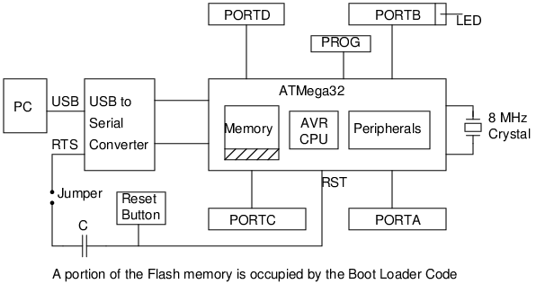
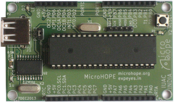
All the external connections to the micro-controller are done through the four external connectors. In addition to the I/O port pins, Ground and the 5 volt supply from USB are available on each connector.
Several plug-in boards are also available.